PDGuide - The Desktop Management Interface (DMI)
Reprint Courtesy of International Business Machines Corporation, © International Business Machines Corporation
This chapter provides background about the DMI, information about the relationship between DMI and VPD (vital product data) and coding examples.
DMI Overview
The Desktop Management Interface (DMI) provides the means for software and hardware components to define VPD information. DMI also provides a standard function set that management applications can use to access that information.
The DMI consists of four elements:
- Format for describing information
- Format for data transfer
- Mechanism for data transfer
- Set of services for facilitating communication
You define component descriptions in a language that is called the Management Information Format (MIF). Each component has a MIF file that describes the manageable characteristics of the component.
Component providers use the Component Interface (CI) to describe how to access management information and enable a component to be managed.
Applications use the Management Interface (MI) to manage components.
The CI and MI are data interfaces, as opposed to procedural interfaces.
The Service Layer (SL) is an active, resident code that runs on the system. The SL mediates between the MI and the CI and performs services on behalf of each.
The DMI is a local interface that is used within a single system. DMI does not replace existing network management protocols. DMI provides a consistent method for providing instrumentation to those protocols. The Service Layer is the broker of local instrumentation.
DMI provides the following:
- Independence of a specific computer, operating system, or management protocol
- An easily adopted interface for application developers
- Does not require a network
- Mapping to existing management protocols.
The DMI does not address or specify a protocol for management over a network.
DMI Structure
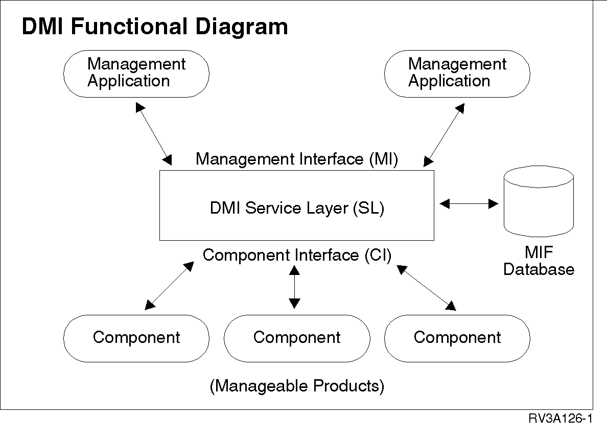
The DMI is a local interface for single-system use, regardless of being a standalone desktop system or part of a network. The interface consists of the following parts:
- Service Layer (SL): A local program that collects and manages product information in the MIF database. The Service Layer distributes requested information to management applications through the Management Interface (MI) and to manageable products through the Component Interface (CI).
- MIF database: The database containing the installed or attached manageable product information. MIF files contain the information, and the Service Layer manages the information.
- Management applications: Remote or local programs used to interrogate, track, control, and list the elements of a desktop system. A management application can be any of the following:
- a graphical user interface program
- a network management agent
- an installer program
- a diagnostics program
- a remote procedure call.
- Manageable products: Components that are connected to or part of a desktop computer system or network server. Components can be part of the system code, or you can add them later. Each product has a MIF file in the MIF database that contains pertinent product management information.
The following figure shows the DMI structure:
DMIFunctionalDiagram
