OpenGL on OS/2 - All About NURBS: Difference between revisions
No edit summary |
No edit summary |
||
| Line 1: | Line 1: | ||
Written by [[Perry Newhook]] | ''Written by [[Perry Newhook]]'' | ||
=All About NURBS= | |||
==Introduction== | ==Introduction== | ||
Well here we are again with another month of OpenGL programming. As promised, this month we describe NURBS, what they are for, and most importantly, how to use them. I hope everyone benefitted from last month's column. In it we described the different toolkits available to OpenGL programmers such as yourselves, so that you don't have to rely on any one compiler (or platform for that matter,) to create your applications. | Well here we are again with another month of OpenGL programming. As promised, this month we describe NURBS, what they are for, and most importantly, how to use them. I hope everyone benefitted from last month's column. In it we described the different toolkits available to OpenGL programmers such as yourselves, so that you don't have to rely on any one compiler (or platform for that matter,) to create your applications. | ||
==Background== | ==Background== | ||
Ok, here we go. Before getting into the OpenGL implementation of NURBS, I will give a bit of background as to what they actually are. Since this is almost impossible without at least a bit of math, those who are not mathematically inclined can simply skip to the next section. Even if you don't like the math, this section will be useful because to create the effect that you want, you have to understand at least a bit of what is going on underneath. However, since this is not a computer science course, I will try to keep the math to only what is necessary. | Ok, here we go. Before getting into the OpenGL implementation of NURBS, I will give a bit of background as to what they actually are. Since this is almost impossible without at least a bit of math, those who are not mathematically inclined can simply skip to the next section. Even if you don't like the math, this section will be useful because to create the effect that you want, you have to understand at least a bit of what is going on underneath. However, since this is not a computer science course, I will try to keep the math to only what is necessary. | ||
| Line 18: | Line 16: | ||
==Evaluators== | ==Evaluators== | ||
OpenGL evaluators always make splines and surfaces based on a Bezier basis. If you create evaluators that use some other basis, they must be converted to a Bezier basis before you can use them with OpenGL. What is a Bezier function? Well, I'm glad you asked. | OpenGL evaluators always make splines and surfaces based on a Bezier basis. If you create evaluators that use some other basis, they must be converted to a Bezier basis before you can use them with OpenGL. What is a Bezier function? Well, I'm glad you asked. | ||
A Bezier curve is a vector based function of one variable in the form: | A Bezier curve is a vector based function of one variable in the form: | ||
C(u) = [ X(u) Y(u) Z(u) ] | |||
and a Bezier surface is a vector valued function of two variables: | |||
S(u,v) = [ X(u,v) Y(u,v) Z(u,v) ] | |||
and a Bezier surface is a vector valued function of two variables: | |||
For each u (and v for surfaces) C() and S() calculates a point on the curve or surface. To use an evaluator, define and enable a function C() or S() that you wish to use, and where you normally call glVertex(), call glEvalCoord1() or glEvalCoord2() instead. | For each u (and v for surfaces) C() and S() calculates a point on the curve or surface. To use an evaluator, define and enable a function C() or S() that you wish to use, and where you normally call glVertex(), call glEvalCoord1() or glEvalCoord2() instead. | ||
| Line 46: | Line 38: | ||
which is what is used by glMap1(). | which is what is used by glMap1(). | ||
glMap1() is defined as follows: | glMap1() is defined as follows: | ||
glMap1( GLenum target, TYPE u1, TYPE u2, GLint stride, | |||
GLint order, const TYPE *points ) | |||
* target defines what the points represent, which can be vertices, colours, normals, or texture coordinates. This type must also be enabled or disabled with glEnable() or glDisable() in order to use it. | * target defines what the points represent, which can be vertices, colours, normals, or texture coordinates. This type must also be enabled or disabled with glEnable() or glDisable() in order to use it. | ||
* u1 and u2 indicate the range of the variable u. | * u1 and u2 indicate the range of the variable u. | ||
| Line 58: | Line 47: | ||
* points is a pointer to the list of control points | * points is a pointer to the list of control points | ||
Example code of how to use the above could be: | Example code of how to use the above could be: | ||
(inside initialization code) | (inside initialization code) | ||
// initialize and enable the evaluators | // initialize and enable the evaluators | ||
| Line 70: | Line 57: | ||
for( int i=0; i<NUM_SEGMENTS; i++ ) | for( int i=0; i<NUM_SEGMENTS; i++ ) | ||
glEvalCoord1f( (GLfloat)i / NUM_SEGMENTS ); | glEvalCoord1f( (GLfloat)i / NUM_SEGMENTS ); | ||
in the above, ctrlPoints would be a pointer to an array of four XYZ points. | in the above, ctrlPoints would be a pointer to an array of four XYZ points. | ||
Two dimensional evaluators are very similar, except where before we had just u, we now have u and v. This defines a surface instead of just a line. Instead of glMap1() and glEvalCoord1(), we call glMap2() and glEvalCoord2(). glMap2() has the following parameters: | Two dimensional evaluators are very similar, except where before we had just u, we now have u and v. This defines a surface instead of just a line. Instead of glMap1() and glEvalCoord1(), we call glMap2() and glEvalCoord2(). glMap2() has the following parameters: | ||
glMap2( GLenum target, TYPE u1, TYPE u2, GLint ustride, | glMap2( GLenum target, TYPE u1, TYPE u2, GLint ustride, | ||
GLint uorder, TYPE v1, TYPE v2, GLint vstride, | GLint uorder, TYPE v1, TYPE v2, GLint vstride, | ||
GLint vorder, const TYPE *points ) | GLint vorder, const TYPE *points ) | ||
the parameters mean exactly what they meant with glMap1() but now we have independent settings for both u and v. | the parameters mean exactly what they meant with glMap1() but now we have independent settings for both u and v. | ||
==GLU NURBS Interface== | ==GLU NURBS Interface== | ||
Instead of using evaluators directly, most applications use the NURBS interface provided by the OpenGL utility library. This interface removes much of the math from creating NURBS and hides it behind a few very simple to use functions. | Instead of using evaluators directly, most applications use the NURBS interface provided by the OpenGL utility library. This interface removes much of the math from creating NURBS and hides it behind a few very simple to use functions. | ||
Before calling any of the NURBS functions, we have to tell OpenGL that we are going to create a NURB. To do this simply call the function | Before calling any of the NURBS functions, we have to tell OpenGL that we are going to create a NURB. To do this simply call the function | ||
nurbSurface = gluNewNurbsRenderer(); | |||
Every call to this function returns a pointer to a GLUnurbsObj, that must be used with each of the other NURBS interface functions. In this manner we can create any number of individual NURBS patches, and set properties for each independently. | Every call to this function returns a pointer to a GLUnurbsObj, that must be used with each of the other NURBS interface functions. In this manner we can create any number of individual NURBS patches, and set properties for each independently. | ||
To set the properties, we call (duh), gluNurbsProperty(). | To set the properties, we call (duh), gluNurbsProperty(). | ||
gluNurbsProperty( GLUnurbsObj *nurb, GLenum property, GLfloat value ); | |||
property can be one of the following | property can be one of the following | ||
| Line 107: | Line 85: | ||
: value is Boolean. GL_TRUE means that the NURBS code automatically uses the current projection, modelview and viewport matrices to compute sampling and culling matrices for each curve rendered. GL_FALSE requires the user to specify matrices with gluLoadSamplingMatrices(). | : value is Boolean. GL_TRUE means that the NURBS code automatically uses the current projection, modelview and viewport matrices to compute sampling and culling matrices for each curve rendered. GL_FALSE requires the user to specify matrices with gluLoadSamplingMatrices(). | ||
For our example we will set the tolerance down to 25, and specify that the nurbs should be filled in. | For our example we will set the tolerance down to 25, and specify that the nurbs should be filled in. | ||
gluNurbsProperty( nurbSurface, GLU_SAMPLING_TOLERANCE, 25.0 ); | gluNurbsProperty( nurbSurface, GLU_SAMPLING_TOLERANCE, 25.0 ); | ||
gluNurbsProperty( nurbSurface, GLU_DISPLAY_MODE, GLU_FILL ); | gluNurbsProperty( nurbSurface, GLU_DISPLAY_MODE, GLU_FILL ); | ||
Now that we have the NURB set up, we just have to call the code that actually displays it. All NURB drawing functions have to be surrounded by a gluBeginSurface(), gluEndSurface() pair. The only parameter that these functions take is the pointer to the NURB object returned above. | Now that we have the NURB set up, we just have to call the code that actually displays it. All NURB drawing functions have to be surrounded by a gluBeginSurface(), gluEndSurface() pair. The only parameter that these functions take is the pointer to the NURB object returned above. | ||
The surface is actually drawn with the function gluNurbsSurface(). | The surface is actually drawn with the function gluNurbsSurface(). | ||
gluNurbsSurface( GLUnurbsObj *nurb, GLint uKnotCount, GLfloat *uKnot, | gluNurbsSurface( GLUnurbsObj *nurb, GLint uKnotCount, GLfloat *uKnot, | ||
GLint vKnotCount, GLfloat *vKnot, GLint uStride, | GLint vKnotCount, GLfloat *vKnot, GLint uStride, | ||
| Line 134: | Line 107: | ||
* type specifies the type of surface which can be any valid two dimensional evaluator type such as GL_MAP2_VERTEX_3 or GL_MAP2_COLOR_4 | * type specifies the type of surface which can be any valid two dimensional evaluator type such as GL_MAP2_VERTEX_3 or GL_MAP2_COLOR_4 | ||
If you wish to draw a curved line instead of a surface, you can call gluNurbsCurve(). The parameters have the same meaning as gluNurbsSurface() except there is only a u direction because it is one-dimensional. | If you wish to draw a curved line instead of a surface, you can call gluNurbsCurve(). The parameters have the same meaning as gluNurbsSurface() except there is only a u direction because it is one-dimensional. | ||
gluNurbsCurve( GLUnurbsObj *nurb, GLint uKnotCount, GLfloat *uKnot, | gluNurbsCurve( GLUnurbsObj *nurb, GLint uKnotCount, GLfloat *uKnot, | ||
GLint uStride, GLfloat *cttrlArray, GLint uOrder, | GLint uStride, GLfloat *cttrlArray, GLint uOrder, | ||
GLenum type ); | GLenum type ); | ||
For an example that has 26 knots and thirteen control points in each of the u and v directions, the code could look like: | For an example that has 26 knots and thirteen control points in each of the u and v directions, the code could look like: | ||
gluBeginSurface( nurbSurface ); | gluBeginSurface( nurbSurface ); | ||
gluNurbsSurface( nurbSurface, 26, knots, 26, knots, 13*3, 3, | gluNurbsSurface( nurbSurface, 26, knots, 26, knots, 13*3, 3, | ||
&points[0][0][0], 13, 13, GL_MAP2_VERTEX_3 ); | &points[0][0][0], 13, 13, GL_MAP2_VERTEX_3 ); | ||
gluEndSurface( nurbSurface ); | gluEndSurface( nurbSurface ); | ||
Complete source code fo a simple example can be downloaded [glcol12a.zip here]. For this sample we used the control points shown in the following image: | |||
Complete source code fo a simple example can be downloaded [glcol12a.zip | |||
[[Image:OpenGL-points.gif]] | [[Image:OpenGL-points.gif]] | ||
| Line 168: | Line 136: | ||
==NURBS Trimming== | ==NURBS Trimming== | ||
While a NURBS patch may follow the desired shape, the patch itself may extend outside of the desired render area. This is because the NURBS patch can be thought of as a rectangular rubber sheet stretched over the control points. While the sheet does stretch to the correct shape, the edges are still rectangular. The NURBS interface allows you to trim away any section, or multiple sections that are unwanted, leaving only the desired surface. | While a NURBS patch may follow the desired shape, the patch itself may extend outside of the desired render area. This is because the NURBS patch can be thought of as a rectangular rubber sheet stretched over the control points. While the sheet does stretch to the correct shape, the edges are still rectangular. The NURBS interface allows you to trim away any section, or multiple sections that are unwanted, leaving only the desired surface. | ||
Trimming is performed by specifying a gluNurbsCurve() or a gluPwlCurve(). Since gluNurbsCurve() was described above, I will describe gluPwlCurve() here. | Trimming is performed by specifying a gluNurbsCurve() or a gluPwlCurve(). Since gluNurbsCurve() was described above, I will describe gluPwlCurve() here. | ||
gluPwlCurve() creates a piecewise linear trimming curve for the NURBS object. | gluPwlCurve() creates a piecewise linear trimming curve for the NURBS object. | ||
gluPwlCurve( GLUnurbsObj *nurb, GLint count, GLfloat *array, | gluPwlCurve( GLUnurbsObj *nurb, GLint count, GLfloat *array, | ||
GLint stride, GLenum type ); | GLint stride, GLenum type ); | ||
| Line 187: | Line 152: | ||
A trimming curve has to be surrounded by a gluBeginTrim(), gluEndTrim() pair, and because the trimming commands operate on the nurb, the commands must occur between the gluBeginSurface() and gluEndSurface() pair as well. | A trimming curve has to be surrounded by a gluBeginTrim(), gluEndTrim() pair, and because the trimming commands operate on the nurb, the commands must occur between the gluBeginSurface() and gluEndSurface() pair as well. | ||
For the surface above, if we picked eight values for a trim curve, the resulting code could look like: | For the surface above, if we picked eight values for a trim curve, the resulting code could look like: | ||
gluBeginSurface( nurbSurface ); | gluBeginSurface( nurbSurface ); | ||
gluNurbsSurface( nurbSurface, ... ); | gluNurbsSurface( nurbSurface, ... ); | ||
| Line 197: | Line 160: | ||
gluEndTrim( nurbSurface ); | gluEndTrim( nurbSurface ); | ||
gluEndSurface( nurbSurface ); | gluEndSurface( nurbSurface ); | ||
To determine what is included and what is thrown away, simply remember that everything to the left is kept and everything to the right is trimmed. Curves have to be closed and if multiple curves are specified, then they cannot intersect. You can cut multiple holes out, and you can also create islands within holes by creating a curve in the opposite direction within a trimmed out section. | To determine what is included and what is thrown away, simply remember that everything to the left is kept and everything to the right is trimmed. Curves have to be closed and if multiple curves are specified, then they cannot intersect. You can cut multiple holes out, and you can also create islands within holes by creating a curve in the opposite direction within a trimmed out section. | ||
| Line 203: | Line 165: | ||
==Conclusion== | ==Conclusion== | ||
Well that's it for this month. Be sure to check back again next time when we create a full application from start to finish, one that I'm sure you'll all enjoy. | Well that's it for this month. Be sure to check back again next time when we create a full application from start to finish, one that I'm sure you'll all enjoy. | ||
[[Category:Languages Articles]] | [[Category:Languages Articles]] | ||
Revision as of 21:34, 11 March 2017
Written by Perry Newhook
All About NURBS
Introduction
Well here we are again with another month of OpenGL programming. As promised, this month we describe NURBS, what they are for, and most importantly, how to use them. I hope everyone benefitted from last month's column. In it we described the different toolkits available to OpenGL programmers such as yourselves, so that you don't have to rely on any one compiler (or platform for that matter,) to create your applications.
Background
Ok, here we go. Before getting into the OpenGL implementation of NURBS, I will give a bit of background as to what they actually are. Since this is almost impossible without at least a bit of math, those who are not mathematically inclined can simply skip to the next section. Even if you don't like the math, this section will be useful because to create the effect that you want, you have to understand at least a bit of what is going on underneath. However, since this is not a computer science course, I will try to keep the math to only what is necessary.
NURBS stands for Non-Uniform Rational B-Spline. B-Spline is derived from the term basis spline. (Don't you love it when acronyms contain acronyms? If you do, come join the space program.) Now to understand this fully, let's go all the way back and describe the simple curve.
If you recall our OpenGL primitives, you may notice that a curve is not one of them. All we can really do in OpenGL is draw points, and line segments; all other OpenGL objects are made up from them (i.e. a triangle is simply three lines connected together and filled in. A polygon is an n-sided "triangle".) The curves that we have encountered so far are simply segmented with lines; the shorter the line segments the more accurate the curve. You would have noticed this with our previous examples when we used a wire cylinder and wire sphere.
If we wanted a really accurate curve so that we could not visually see the individual segments, we would need to specify a lot of individual line segments. If we wanted to show a smooth surface, we would have a large number of very small polygons. This would quickly get tedious and impractical for large scenes. Many curves and surfaces, however, can instead be described by a small number of parameters in a mathematical formula. A third order function would describe a unique curve with only three parameters. Such a surface could be described with nine parameters, and take up much less storage space than the equivalent surface described with polygons. The polygon surface would also only approximate the surface (because at some scale it still consists of flat polygons) while the mathematical version is perfectly accurate. In OpenGL we use evaluators to specify the points on the curve using only the control points.
Evaluators
OpenGL evaluators always make splines and surfaces based on a Bezier basis. If you create evaluators that use some other basis, they must be converted to a Bezier basis before you can use them with OpenGL. What is a Bezier function? Well, I'm glad you asked.
A Bezier curve is a vector based function of one variable in the form:
C(u) = [ X(u) Y(u) Z(u) ]
and a Bezier surface is a vector valued function of two variables:
S(u,v) = [ X(u,v) Y(u,v) Z(u,v) ]
For each u (and v for surfaces) C() and S() calculates a point on the curve or surface. To use an evaluator, define and enable a function C() or S() that you wish to use, and where you normally call glVertex(), call glEvalCoord1() or glEvalCoord2() instead.
The definition of the evaluator is done with the functions glMap1() for a one dimensional evaluator (a line) or glMap2() for a two dimensional evaluator (a surface). glMap1() uses the following equations that define a curve:
represents a Bernstein polynomial of degree n. Now if Pi represents a set of control points then:
represents a Bezier curve as u varies from 0 to 1. To allow the same curve to vary from u1 to u2 instead of 0 to 1, evaluate:
which is what is used by glMap1().
glMap1() is defined as follows:
glMap1( GLenum target, TYPE u1, TYPE u2, GLint stride,
        GLint order, const TYPE *points )
- target defines what the points represent, which can be vertices, colours, normals, or texture coordinates. This type must also be enabled or disabled with glEnable() or glDisable() in order to use it.
- u1 and u2 indicate the range of the variable u.
- stride is the number of values between control points
- order is the degree of the polynomial plus 1 and should be equal to the number of control points
- points is a pointer to the list of control points
Example code of how to use the above could be:
  (inside initialization code)
  // initialize and enable the evaluators
  glMap1f( GL_MAP1_VERTEX_3, 0.0, 1.0, 3, 4, ctrlPoints );
  glEnable( GL_MAP1_VERTEX_3 );

  (inside paint routine)
  glBegin( GL_LINE_STRIP );
  for( int i=0; i<NUM_SEGMENTS; i++ )
          glEvalCoord1f( (GLfloat)i / NUM_SEGMENTS );
in the above, ctrlPoints would be a pointer to an array of four XYZ points.
Two dimensional evaluators are very similar, except where before we had just u, we now have u and v. This defines a surface instead of just a line. Instead of glMap1() and glEvalCoord1(), we call glMap2() and glEvalCoord2(). glMap2() has the following parameters:
   glMap2( GLenum target, TYPE u1, TYPE u2, GLint ustride,
           GLint uorder, TYPE v1, TYPE v2, GLint vstride,
           GLint vorder, const TYPE *points )
the parameters mean exactly what they meant with glMap1() but now we have independent settings for both u and v.
GLU NURBS Interface
Instead of using evaluators directly, most applications use the NURBS interface provided by the OpenGL utility library. This interface removes much of the math from creating NURBS and hides it behind a few very simple to use functions.
Before calling any of the NURBS functions, we have to tell OpenGL that we are going to create a NURB. To do this simply call the function
nurbSurface = gluNewNurbsRenderer();
Every call to this function returns a pointer to a GLUnurbsObj, that must be used with each of the other NURBS interface functions. In this manner we can create any number of individual NURBS patches, and set properties for each independently.
To set the properties, we call (duh), gluNurbsProperty().
gluNurbsProperty( GLUnurbsObj *nurb, GLenum property, GLfloat value );
property can be one of the following
- GLU_SAMPLING_TOLERANCE
- value specifies the maximum length in pixels of polygon edges. The smaller the number, the smoother looking the final image is but conversely, the longer it takes to render. The default is 50 pixels.
- GLU_DISPLAY_MODE
- defines how a NURB should be rendered. value can be any one of the following: GLU_FILL, GLU_OUTLINE_POLYGON, or GLU_OUTLINE_PATCH
- GLU_CULLING
- value is a Boolean. GL_TRUE means that a NURBS curve should be discarded prior to tesselation if its control points lie outside the current viewpoint. Default is GL_FALSE.
- GLU_AUTO_LOAD_MATRIX
- value is Boolean. GL_TRUE means that the NURBS code automatically uses the current projection, modelview and viewport matrices to compute sampling and culling matrices for each curve rendered. GL_FALSE requires the user to specify matrices with gluLoadSamplingMatrices().
For our example we will set the tolerance down to 25, and specify that the nurbs should be filled in.
  gluNurbsProperty( nurbSurface, GLU_SAMPLING_TOLERANCE, 25.0 );
  gluNurbsProperty( nurbSurface, GLU_DISPLAY_MODE, GLU_FILL );
Now that we have the NURB set up, we just have to call the code that actually displays it. All NURB drawing functions have to be surrounded by a gluBeginSurface(), gluEndSurface() pair. The only parameter that these functions take is the pointer to the NURB object returned above.
The surface is actually drawn with the function gluNurbsSurface().
  gluNurbsSurface( GLUnurbsObj *nurb, GLint uKnotCount, GLfloat *uKnot,
                   GLint vKnotCount, GLfloat *vKnot, GLint uStride,
                   GLint vStride, GLfloat *ctrlArray, GLint uOrder,
                   GLint vOrder, GLenum type );
- nurb is the pointer to the NURBS object
- uKnotCount specifies the number of knots in the parametric u direction
- uKnot specifies an array of nondecreasing knot values in the u direction
- vKnotCount specifies the number of knots in the parametric v direction
- vKnot specifies an array of nondecreasing knot values in the v direction
- uStride specifies an offset between successive control points in the parametric u direction in ctrlArray
- vStride specifies an offset between successive control points in the parametric v direction in ctrlArray
- uOrder specifies the order of the NURBS surface in the u direction
- vOrder specifies the order of the NURBS surface in the v direction
- type specifies the type of surface which can be any valid two dimensional evaluator type such as GL_MAP2_VERTEX_3 or GL_MAP2_COLOR_4
If you wish to draw a curved line instead of a surface, you can call gluNurbsCurve(). The parameters have the same meaning as gluNurbsSurface() except there is only a u direction because it is one-dimensional.
  gluNurbsCurve( GLUnurbsObj *nurb, GLint uKnotCount, GLfloat *uKnot,
                 GLint uStride, GLfloat *cttrlArray, GLint uOrder,
                 GLenum type );
For an example that has 26 knots and thirteen control points in each of the u and v directions, the code could look like:
  gluBeginSurface( nurbSurface );
  gluNurbsSurface( nurbSurface, 26, knots, 26, knots, 13*3, 3,
                   &points[0][0][0], 13, 13, GL_MAP2_VERTEX_3 );
  gluEndSurface( nurbSurface );
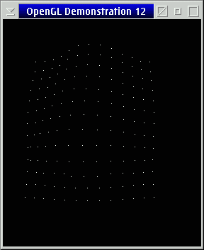
Complete source code fo a simple example can be downloaded [glcol12a.zip here]. For this sample we used the control points shown in the following image:
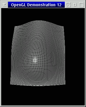
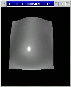
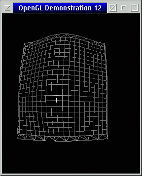
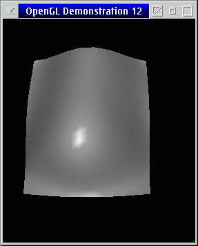
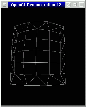
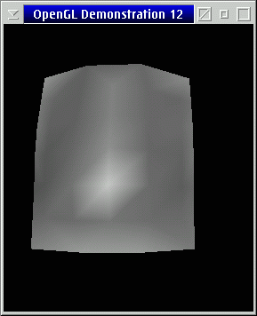
As we stated before, we can vary the quality of the rendered image by varying the NURB sampling tolerance. The following images show the resulting NURB in mesh and in solid form for varying tolerance values.
GLU_SAMPLING_TOLERANCE of 5:
GLU_SAMPLING_TOLERANCE of 25:
GLU_SAMPLING_TOLERANCE of 100:
NURBS Trimming
While a NURBS patch may follow the desired shape, the patch itself may extend outside of the desired render area. This is because the NURBS patch can be thought of as a rectangular rubber sheet stretched over the control points. While the sheet does stretch to the correct shape, the edges are still rectangular. The NURBS interface allows you to trim away any section, or multiple sections that are unwanted, leaving only the desired surface.
Trimming is performed by specifying a gluNurbsCurve() or a gluPwlCurve(). Since gluNurbsCurve() was described above, I will describe gluPwlCurve() here.
gluPwlCurve() creates a piecewise linear trimming curve for the NURBS object.
  gluPwlCurve( GLUnurbsObj *nurb, GLint count, GLfloat *array,
               GLint stride, GLenum type );
- nurb is the pointer to the nurb object
- count specifies the number of points on the curve
- array specifies the array containing the curve points
- stride specifies an offset between points on the curve
- type specifies the type of the curve and can be one of GLU_MAP1_TRIM_2 or GLU_MAP1_TRIM_3
A trimming curve has to be surrounded by a gluBeginTrim(), gluEndTrim() pair, and because the trimming commands operate on the nurb, the commands must occur between the gluBeginSurface() and gluEndSurface() pair as well.
For the surface above, if we picked eight values for a trim curve, the resulting code could look like:
  gluBeginSurface( nurbSurface );
  gluNurbsSurface( nurbSurface, ... );

  gluBeginTrim( nurbSurface );
    gluPwlCurve( nurbSurface, 8, (GLfloat *)trim, 2, GLU_MAP1_TRIM_2 );
  gluEndTrim( nurbSurface );
  gluEndSurface( nurbSurface );
To determine what is included and what is thrown away, simply remember that everything to the left is kept and everything to the right is trimmed. Curves have to be closed and if multiple curves are specified, then they cannot intersect. You can cut multiple holes out, and you can also create islands within holes by creating a curve in the opposite direction within a trimmed out section.
The complete code that shows trimming can be downloaded [glcol12trim.zip here ].
Conclusion
Well that's it for this month. Be sure to check back again next time when we create a full application from start to finish, one that I'm sure you'll all enjoy.


