GPIGuide - Paths: Difference between revisions
Created page with "{{IBM-Reprint}} {{GPIGuide}} A '''path''' is a graphics object composed of one or more figures drawn with graphic primitives. A path can be used for defining a filled area, a complex clipping shape, an outline, and for drawing geometric wide lines. The following topics are related to information in this chapter: * Presentation spaces and device contexts * Line and arc primitives * Area primitives * Color and mix attributes * Regions * Clipping == About Paths == Paths..." |
|||
| (2 intermediate revisions by the same user not shown) | |||
| Line 19: | Line 19: | ||
* The only means of drawing lines with a thickness that can be transformed | * The only means of drawing lines with a thickness that can be transformed | ||
These techniques are respectively illustrated in the following figures: [[File: | These techniques are respectively illustrated in the following figures: | ||
[[File:GPIPaths_66.png|Drawing Techniques Achieved with Paths]] | |||
A path is similar to an area, but there are fundamental differences between the two. The following table describes their similarities and contrasts. | A path is similar to an area, but there are fundamental differences between the two. The following table describes their similarities and contrasts. | ||
| Line 106: | Line 107: | ||
In the floor plan shown in the following figure, the outer walls were drawn using geometric lines. All of the other objects were drawn using normal lines. | In the floor plan shown in the following figure, the outer walls were drawn using geometric lines. All of the other objects were drawn using normal lines. | ||
[[File: | [[File:GPIPaths_67.png|Geometric Lines and Normal Lines]] | ||
Your application can determine the current geometric width by calling [[GpiQueryLineWidthGeom]]. | Your application can determine the current geometric width by calling [[GpiQueryLineWidthGeom]]. | ||
| Line 137: | Line 137: | ||
The following figure illustrates these three types of line ends. Your application can determine the current geometric line end by calling [[GpiQueryLineEnd]]. | The following figure illustrates these three types of line ends. Your application can determine the current geometric line end by calling [[GpiQueryLineEnd]]. | ||
[[File: | [[File:GPIPaths_68.png|Closing Unattached Geometric Lines]] | ||
Closing Unattached Geometric Lines | |||
A square line end extends the line by a distance that is half the width of the line. For example, if the line is six coordinate units wide, a square line end extends it by three coordinate units. | A square line end extends the line by a distance that is half the width of the line. For example, if the line is six coordinate units wide, a square line end extends it by three coordinate units. | ||
| Line 170: | Line 168: | ||
Your application can determine the current geometric line join using [[GpiQueryLineJoin]]. | Your application can determine the current geometric line join using [[GpiQueryLineJoin]]. | ||
[[File: | [[File:GPIPaths_69.png|Joining Wide Lines]] | ||
Joining Wide Lines | |||
=== Cosmetic Line Attributes for Paths === | === Cosmetic Line Attributes for Paths === | ||
| Line 201: | Line 197: | ||
The color attribute defines the color used to draw a primitive or an object. The mix attribute determines how the color of a primitive or an object is combined with the color of the drawing surface, or any other objects on the surface. Unlike the color and mix attributes for primitives, and certain other objects, the path color is defined by different attributes in different situations, as illustrated in the following figure. | The color attribute defines the color used to draw a primitive or an object. The mix attribute determines how the color of a primitive or an object is combined with the color of the drawing surface, or any other objects on the surface. Unlike the color and mix attributes for primitives, and certain other objects, the path color is defined by different attributes in different situations, as illustrated in the following figure. | ||
[[File: | [[File:GPIPaths_70.png|Path Objects]] | ||
Path colors are determined by the area color, area background color, area mix, and area background mix attributes if the path is stroked into a wide line. The cosmetic line path color is determined by the line color and mix attributes. | Path colors are determined by the area color, area background color, area mix, and area background mix attributes if the path is stroked into a wide line. The cosmetic line path color is determined by the line color and mix attributes. | ||
| Line 304: | Line 298: | ||
The first time your application calls [[GpiSetClipPath]], the current path definition is converted into the current clip path. [[GpiSetClipPath]] deletes the path definition upon completion but not the clip path definition. | The first time your application calls [[GpiSetClipPath]], the current path definition is converted into the current clip path. [[GpiSetClipPath]] deletes the path definition upon completion but not the clip path definition. | ||
A path definition can be stored in a graphics segment and, if that segment is retained, Whe path can be re-created as required. Segments are discussed in [[Creating and Drawing Retained Graphics]]. | A path definition can be stored in a graphics segment and, if that segment is retained, Whe path can be re-created as required. Segments are discussed in '''[[GPIGuide - Creating and Drawing Retained Graphics|Creating and Drawing Retained Graphics]]'''. | ||
=== Path Outline === | === Path Outline === | ||
| Line 351: | Line 345: | ||
The following figure shows two identical paths that were filled, each using one of the two modes. Each path consists of a triangle drawn within a rectangle. The path on the left was filled using the alternate mode. The path on the right was filled using the winding mode. | The following figure shows two identical paths that were filled, each using one of the two modes. Each path consists of a triangle drawn within a rectangle. The path on the left was filled using the alternate mode. The path on the right was filled using the winding mode. | ||
[[File: | [[File:GPIPaths_71.png|Alternate and Winding Fill Modes]] | ||
Alternate and Winding Fill Modes | |||
==== Paths in Alternate Mode ==== | ==== Paths in Alternate Mode ==== | ||
| Line 363: | Line 355: | ||
The following figure shows how the operating system determines the filled portion for the path shown in the previous figure. The path outside the triangle, but inside the rectangle, is filled, because the imaginary lines drawn from those points in the positive x-direction intersect the path boundaries an odd number of times. | The following figure shows how the operating system determines the filled portion for the path shown in the previous figure. The path outside the triangle, but inside the rectangle, is filled, because the imaginary lines drawn from those points in the positive x-direction intersect the path boundaries an odd number of times. | ||
[[File: | [[File:GPIPaths_72.png|Calculating Filled Paths Constructed in Alternate Mode]] | ||
Calculating Filled Paths Constructed in Alternate Mode | |||
Parts of the path with odd tallies are filled; parts with even tallies are not filled. | Parts of the path with odd tallies are filled; parts with even tallies are not filled. | ||
| Line 381: | Line 371: | ||
The following figure shows how the operating system determines the filled portion for the path shown in the figure before the previous one. Assume that both the rectangle and triangle were drawn in the same direction, whether clockwise or counterclockwise is immaterial. Both figures are filled, because the number of times the imaginary lines drawn from those points in the positive x-direction intersect the path boundaries is continuously summed. There is never a subtraction of a boundary tally to reduce the total to 0. | The following figure shows how the operating system determines the filled portion for the path shown in the figure before the previous one. Assume that both the rectangle and triangle were drawn in the same direction, whether clockwise or counterclockwise is immaterial. Both figures are filled, because the number of times the imaginary lines drawn from those points in the positive x-direction intersect the path boundaries is continuously summed. There is never a subtraction of a boundary tally to reduce the total to 0. | ||
[[File: | [[File:GPIPaths_73.png|Paths Constructed in the Same Direction in Winding Mode]] | ||
Paths Constructed in the Same Direction in Winding Mode | |||
Parts of the path with nonzero tallies are filled; parts with zero tallies are not filled. | Parts of the path with nonzero tallies are filled; parts with zero tallies are not filled. | ||
| Line 389: | Line 377: | ||
If two figures, for example in the following figure, are drawn in different directions, the tally for the inner triangle is 0 and the area looks exactly as it does in alternate mode. | If two figures, for example in the following figure, are drawn in different directions, the tally for the inner triangle is 0 and the area looks exactly as it does in alternate mode. | ||
[[File: | [[File:GPIPaths_74.png|Paths Constructed in Different Directions in Winding Mode]] | ||
Paths Constructed in Different Directions in Winding Mode | |||
Parts of the path with nonzero tallies are filled; parts with zero tallies are not filled. | Parts of the path with nonzero tallies are filled; parts with zero tallies are not filled. | ||
| Line 432: | Line 418: | ||
When the operating system strokes a path, it draws a geometric line of specified width along the original figure that defined the path and then fills the wide line. If the original figure is not a closed shape, the operating system does not automatically close it before filling the path. The following figure shows the effects of [[GpiStrokePath]] on a box originally defined with normal (cosmetic) lines. | When the operating system strokes a path, it draws a geometric line of specified width along the original figure that defined the path and then fills the wide line. If the original figure is not a closed shape, the operating system does not automatically close it before filling the path. The following figure shows the effects of [[GpiStrokePath]] on a box originally defined with normal (cosmetic) lines. | ||
[[File: | [[File:GPIPaths_75.png|Defining Lines with a Geometric Width]] | ||
Defining Lines with a Geometric Width | |||
The broken line is the figure defined within the path. The solid lines show the path after it has been converted. Each line has a geometric width of '''n''' coordinate units, and the line joins have been defined as beveled. | The broken line is the figure defined within the path. The solid lines show the path after it has been converted. Each line has a geometric width of '''n''' coordinate units, and the line joins have been defined as beveled. | ||
| Line 464: | Line 448: | ||
Any open figures within a path are closed automatically. The boundaries of the path are considered part of the interior, so any point on the boundary is not clipped. The following figure shows the result of clipping text with a triangular clip path. | Any open figures within a path are closed automatically. The boundaries of the path are considered part of the interior, so any point on the boundary is not clipped. The following figure shows the result of clipping text with a triangular clip path. | ||
[[File: | [[File:GPIPaths_76.png|Triangular Clip Path]] | ||
=== Path Conversion to Region === | === Path Conversion to Region === | ||
Latest revision as of 04:28, 14 May 2025
Reprint Courtesy of International Business Machines Corporation, © International Business Machines Corporation
A path is a graphics object composed of one or more figures drawn with graphic primitives. A path can be used for defining a filled area, a complex clipping shape, an outline, and for drawing geometric wide lines.
The following topics are related to information in this chapter:
- Presentation spaces and device contexts
- Line and arc primitives
- Area primitives
- Color and mix attributes
- Regions
- Clipping
About Paths
Paths provide several useful drawing techniques including:
- An alternate means of generating filled or outlined irregular figures and nonrectangular shapes
- An efficient means of producing hollow text in an outline font
- The only means of clipping (restricting the area of interest of a picture) to circular, elliptical, or other nonrectangular figures
- The only means of drawing lines with a thickness that can be transformed
These techniques are respectively illustrated in the following figures:
A path is similar to an area, but there are fundamental differences between the two. The following table describes their similarities and contrasts.
| Paths | Areas |
|---|---|
| Functions that define a path are bracketed by GpiBeginPath. | Functions that define an area are bracketed by GpiBeginArea. |
| Paths are defined in world coordinates. | Areas are defined in world coordinates. |
| Paths can be modified before being displayed or used for clipping. | Areas are displayed immediately on completion. |
| Paths can be used by applications to perform clipping. | Areas cannot be used as clipping regions. |
| Paths can be converted into graphics objects called regions. | Areas cannot be converted into regions. |
Six operations can be performed on paths, each requiring a separate function:
|
Only two operations can be performed on areas (specified with options when creating the area):
|
Path Attributes
Paths do not have a separate BUNDLE data structure associated with them. Their attributes are defined by LINEBUNDLE and AREABUNDLE. There are certain line attributes that apply only to geometric lines, or lines created with some path operations. Depending on the purpose of a path, only certain path attributes are in effect. These and the other path attributes are described in this chapter.
When an application creates a presentation space, the path attributes are set to the default values shown in the following table.
Path Attribute Default Values
| Attribute | Default Value | Function that Redefines Attribute |
|---|---|---|
| Geometric width | None | GpiSetLineWidthGeom |
| End | LINEEND_FLAT | GpiSetLineEnd |
| Join | LINEJOIN_BEVEL | GpiSetLineJoin |
| Width | 1.0 | GpiSetLineWidth |
| Type | LINETYPE_SOLID | GpiSetLineType |
| Color | CLR_NEUTRAL | GpiSetAttrs (LBB_COLOR) |
| Mix mode | FM_OVERPAINT | GpiSetAttrs (LBB_MIX_MODE) |
| Pattern symbol | Solid | GpiSetPattern |
| Pattern set | LCID_DEFAULT | GpiSetPatternSet |
| Reference point | (0,0) | GpiSetPatternRefPoint |
| Foreground color | CLR_NEUTRAL (black on most devices) | GpiSetAttrs (ABB_COLOR) |
| Background color | CLR_BACKGROUND (white on most devices) | GpiSetAttrs (ABB_BACK_COLOR) |
| Foreground mix | FM_OVERPAINT | GpiSetAttrs (ABB_MIX_MODE) |
| Background mix | BM_LEAVEALONE | GpiSetAttrs (ABB_BACK_MIX_MODE) |
Geometric width, End, and Join take effect only when a path is converted to a geometric wide line using GpiStrokePath or GpiModifyPath. Width, Type, Color, and Mix mode take effect only when a path is outlined using GpiOutlinePath. Pattern symbol, Pattern set, and Reference point take effect only when a path is filled using GpiFillPath or GpiStrokePath.
Line Width and Geometric Width for Paths
Cosmetic lines represent the mathematical ideal of a one-dimensional line. The width attribute associated with them is provided only for ease of drawing these lines larger than one pel.
In contrast, geometric line width is not an attribute; it is a geometric property. To set the width of a geometric line, an application can use GpiSetLineWidthGeom. This geometric width takes effect only when a path is converted to a geometric wide line using GpiStrokePath or GpiModifyPath.
If a geometric line is drawn before the geometric width is specified, the drawn line is defined by the cosmetic line width—usually 1—which results in the thinnest possible line for the currently associated device. A geometric line width has no default in the same way that the sides of a box, drawn with GpiBox, have no length until specified by the function.
The value specified with GpiSetLineWidthGeom is the thickness of the line in world coordinates, and it is subject to scaling by the current transformations in effect at the time GpiModifyPath or GpiStrokePath is called. For example, if you apply a transform with a scaling factor of 0.5, for an object whose current geometric line width is four world coordinates, the width of the displayed line will be halved.
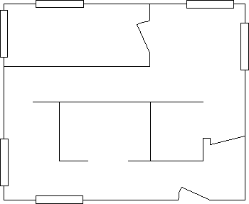
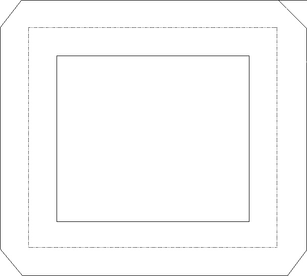
In the floor plan shown in the following figure, the outer walls were drawn using geometric lines. All of the other objects were drawn using normal lines.
Your application can determine the current geometric width by calling GpiQueryLineWidthGeom.
Line End
The line end attribute specifies the shape of the unattached end of a geometric line. Lines whose shapes are partially defined by a geometric width have to be closed, unlike cosmetic lines that simply end. An application can draw geometric lines with square, flat, or round ends.
Note: The end attribute takes effect only when a path is converted to a geometric width line using GpiStrokePath or GpiModifyPath.
Set the current geometric line end attribute with GpiSetLineEnd. The attribute applies to all subsequent unattached lines within the path bracket. The following table describes the three standard line ends provided by the PM programming interface; you cannot define your own end types.
Standard Geometric Line End Types
| Type | Identifier | Long Value |
|---|---|---|
| Flat, flush with line end | LINEEND_FLAT | 1L |
| Round, past line end | LINEEND_ROUND | 2L |
| Flat, but extends past line end | LINEEND_SQUARE | 3L |
The default line end type (LINEEND_DEFAULT) is identical to the LINEEND_FLAT type, and has a long value of 0L. The error linetype (LINEEND_ERROR) has a long value of -1L.
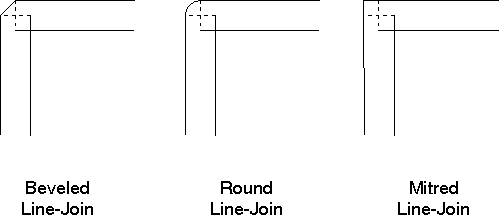
The following figure illustrates these three types of line ends. Your application can determine the current geometric line end by calling GpiQueryLineEnd.
A square line end extends the line by a distance that is half the width of the line. For example, if the line is six coordinate units wide, a square line end extends it by three coordinate units.
A round line end is constructed by drawing a circle whose radius is half the width of the line.
Line Join
The line join attribute specifies the shape formed by two intersecting geometric lines. Where one wide line joins another, the nature of the join must be defined. An application can select a beveled, rounded, or mitred line-join style.
Note: The join attribute takes effect only when a path is converted to a geometric wide line using GpiStrokePath or GpiModifyPath.
Set the current geometric line-join attribute with GpiSetLineJoin. The attribute applies to all subsequent intersection of lines within the path bracket. The following table describes the three standard line joins provided by the PM programming interface. You cannot define your own join types.
Standard Geometric Line Join Types
| Type | Identifier | Long Value |
|---|---|---|
| Diagonal corner | LINEJOIN_BEVEL | 1L |
| Rounded corner | LINEJOIN_ROUND | 2L |
| 90° angled corner | LINEJOIN_MITRE | 3L |
The default join type (LINEJOIN_DEFAULT) is identical to the LINEJOIN_BEVEL type, and has a long value of 0L. The error linetype (LINEJOIN_ERROR) has a long value of -1L. The following figure illustrates these three types of line joins.
Your application can determine the current geometric line join using GpiQueryLineJoin.
Cosmetic Line Attributes for Paths
When a path is drawn as a cosmetic line with GpiOutlinePath, the following attributes are defined by the LINEBUNDLE data structure:
- Line width
- Line type
- Line color
- Line mix
These attributes follow the current definitions and appear just as line primitives do. Since the line primitive has only a foreground color and mix attribute, the current color of the drawing surface affects the appearance of these paths more than it does the appearance of paths that define geometric lines. Those paths follow the area attributes and are affected by background color and background mix attributes as well.
Area Attributes for Paths
When a path is drawn as a geometric line with GpiStrokePath or GpiModifyPath, the following attributes are defined by the AREABUNDLE data structure:
- Pattern symbol
- Pattern set
- Pattern reference point
- Area foreground color
- Area background color
- Area foreground mix
- Area background mix
Area attributes follow the current definitions and appear just as area primitives do. The operating system uses the pattern symbol to fill the interior of the path that defines the geometric line. Any alterations to the fill pattern or reference point affect the appearance of a geometric line just as it does an area.
Path Color and Mix Attributes
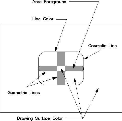
The color attribute defines the color used to draw a primitive or an object. The mix attribute determines how the color of a primitive or an object is combined with the color of the drawing surface, or any other objects on the surface. Unlike the color and mix attributes for primitives, and certain other objects, the path color is defined by different attributes in different situations, as illustrated in the following figure.
Path colors are determined by the area color, area background color, area mix, and area background mix attributes if the path is stroked into a wide line. The cosmetic line path color is determined by the line color and mix attributes.
The line color defines the color used to draw the output from any of the IBM OS/2 line functions called within the path. The line colors can change within the path bracket, just as they can within area brackets. The interaction of the line with the drawing-surface color is controlled by the line mix attribute, which also can vary within the path bracket.
After the path is closed, the path can be stroked into a geometric (or wide) line. Depending on the construction options, the geometric line can be filled. The appearance of the pattern symbol used to fill the path depends on the area attributes. The definitions of the area color and background color depend on the pattern symbol.
Path Brackets
The functions that create and define the path always are bracketed by the GpiBeginPath and GpiEndPath functions. Only one path can be defined between these two functions. However, within the path, there can be any number of figures.
GpiBeginPath signals the start of a path definition. Each path you define becomes the current path and replaces any existing path in the presentation space. The current position is not changed by GpiBeginPath, although it is updated by any drawing instructions that follow.
GpiBeginPath accepts as input only a path identifier of 1. This identifier is used by the functions performing path operations to identify the path.
Due to the number of different operations that can be performed on paths, the path definition can contain both open and closed figures. If a figure does not start and end at the same coordinate point, it is classified as an open figure. Unlike an area bracket, if you use GpiSetCurrentPosition or GpiMove within a path definition, the current figure is not automatically closed.
The PM provides a method of closing figures within a path. GpiCloseFigure (valid only in path brackets) closes a figure in the path whose start and end points are not the same, by drawing a straight line from the current position to the start position of the figure. Use GpiCloseFigure if you want the line join attribute to be applied between the start and end point of a figure. Do not use it if you want the line end attributes to be used as the start and end points for a geometric wide line.
If the path definition contains full arc or box primitives, however, you must not close them using GpiCloseFigure. GpiBox and GpiFullArc generate completely closed figures and must not be used within another figure definition.
To signal the end of the current path definition, use GpiEndPath. The path definition is constructed in the currently associated presentation space. The current position always is updated to the end point of the last line drawn.
The functions that generate a path are enclosed in a path bracket. Applications can use the functions in the following list within a path bracket:
- GpiBeginElement
- GpiBox
- GpiCallSegmentMatrix
- GpiCharString
- GpiCharStringAt
- GpiCharStringPos
- GpiCharStringPosAt
- GpiCloseFigure
- GpiComment
- GpiCreateLogFont
- GpiDeleteSetId
- GpiElement
- GpiEndElement
- GpiEndPath
- GpiFullArc
- GpiGetData
- GpiLabel
- GpiLine
- GpiMarker
- GpiMove
- GpiOffsetElementPointer
- GpiPartialArc
- GpiPointArc
- GpiPolyFillet
- GpiPolyFilletSharp
- GpiPolyLine
- GpiPolyMarker
- GpiPolySpline
- GpiPop
- GpiPutData
- GpiQueryArcParams
- GpiQueryAttrMode
- GpiQueryCurrentPosition
- GpiSetArcParams
- GpiSetAttrMode
- GpiSetAttrs
- GpiSetCharAngle
- GpiSetCharBox
- GpiSetCharDirection
- GpiSetCharMode
- GpiSetCharSet
- GpiSetCharShear
- GpiSetColor
- GpiSetCp
- GpiSetCurrentPosition
- GpiSetEditMode
- GpiSetLineEnd
- GpiSetLineJoin
- GpiSetLineType
- GpiSetLineWidth
- GpiSetMarker
- GpiSetMarkerBox
- GpiSetMarkerSet
- GpiSetMix
- GpiSetModelTransformMatrix
Warning: Some GPI functions cannot be used while an open path definition exists. In particular, you cannot include image or area primitives in a path definition.
Path Operations
The operations performed on a path determine which of the path attributes become applicable. Unlike specifying area brackets, the variety of operations also calls for separate functions instead of specifying options with GpiBeginPath. Specifically, the following six operations can be performed on a path:
- Outline
- Fill
- Modify
- Stroke
- Convert to clip path
- Convert to region
There are other graphics operations provided by the PM—for example, transformations—that can apply to entities other than paths.
Upon completion, GpiFillPath, GpiOutlinePath, GpiStrokePath, and GpiPathToRegion delete the current path definition. This path is not available for any subsequent operations.
GpiModifyPath does not delete the current path definition. An application can modify a path before using one of the aforementioned functions.
The first time your application calls GpiSetClipPath, the current path definition is converted into the current clip path. GpiSetClipPath deletes the path definition upon completion but not the clip path definition.
A path definition can be stored in a graphics segment and, if that segment is retained, Whe path can be re-created as required. Segments are discussed in Creating and Drawing Retained Graphics.
Path Outline
To draw the outline of the current path, use GpiOutlinePath. This function accepts a path identifier (which must be 1) as input. GpiOutlinePath does not create a geometric line; therefore, the cosmetic line attributes are used.
GpiOutlinePath normally has the same effect as though the lines and arcs used to create the path were drawn without actually being part of the path. Any open figures within the path are not closed automatically. If the path contains character strings that use an outline font, the characters are not filled.
The following functional sequence is recommended for drawing outline text or outline figures:
| Function Name | Effect |
|---|---|
| GpiBeginPath | Starts the path definition. |
| GpiMove | Moves to the starting point of the first figure. |
| GpiCharString, GpiFullArc | Uses an outline font to specify text or define the lines in a figure. |
| GpiEndPath | Ends the path. |
| GpiOutlinePath | Draws the text or figure outlines. |
If you are drawing a complex path, consisting of several character strings that use an outline font, it can take quite some time to produce. If you want to create a only rough draft, you might find it quicker to draw an outline instead of the filled path. This improves performance and might be acceptable for small characters. When they are small enough, hollow characters can look like filled characters.
You can create hollow characters in either of two ways:
- Outside a path, call GpiCreateLogFont. This enables you to define an outline font that uses hollow characters.
- Inside a path, draw the characters, then display the path with GpiOutlinePath.
Only the character outlines contribute to the path definition even if the font is not hollow. (This might cause ambiguous results.)
Using outlined paths to create character outlines also can be used to define a clip path in the shape of a letter or word.
Path Fill
To draw the current path and fill its interior using the current pattern symbol, use GpiFillPath. The path is deleted after the interior is filled. The boundary lines are considered part of the path interior and are drawn with this function. Any open figures in the path definition are closed automatically by GpiFillPath.
This function accepts the path identifier (which must be 1) as input, and either of two construction options:
- FPATH_ALTERNATE (the default)
- FPATH_WINDING (must be selected if the path has been modified).
Paths, like area primitives, can be filled in alternate mode or winding mode. If the path consists of multiple, intersecting figures, the path-fill mode affects the final appearance of the path.
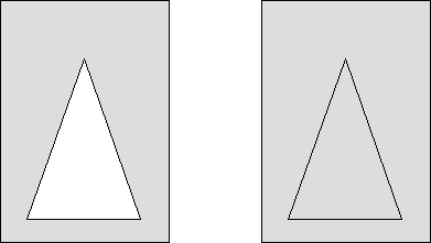
The following figure shows two identical paths that were filled, each using one of the two modes. Each path consists of a triangle drawn within a rectangle. The path on the left was filled using the alternate mode. The path on the right was filled using the winding mode.
Paths in Alternate Mode
For paths drawn in alternate mode (as with area primitives), the following is true:
- If you have to cross an odd number of boundaries in the path when drawing an imaginary line parallel to the x-axis, a point is included in the filled path from that point to positive infinity.
- If you have to cross an even number of boundaries in the path when drawing an imaginary line parallel to the x-axis, a point is not included in the filled path from that point to positive infinity.
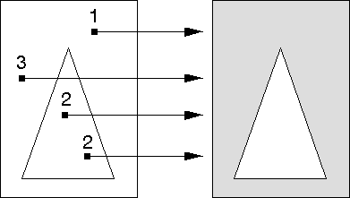
The following figure shows how the operating system determines the filled portion for the path shown in the previous figure. The path outside the triangle, but inside the rectangle, is filled, because the imaginary lines drawn from those points in the positive x-direction intersect the path boundaries an odd number of times.
Parts of the path with odd tallies are filled; parts with even tallies are not filled.
Paths in Winding Mode
For paths drawn in winding mode (also like area primitives), the direction the boundaries in the path are drawn in determines whether a given point is included in the filled path. The drawn direction of a boundary line depends on both the graphics functions used to draw it and the world coordinates that define it.
For box primitives, for example, if the specified diagonal corner is to the right, to the top, or both, of the current position, the box is drawn counterclockwise. If the specified diagonal corner is to the left, to the bottom, but not both, the box is drawn clockwise.
For a polyline primitive, the direction of the boundary depends on the relative values of the start and end points of each line. For a polygon primitive, the direction of the boundary depends on the relative values of the specified vertices.
To determine whether a given point is included in the filled path, count the number of boundary lines to be crossed to move from that point to infinity. For each boundary line drawn in one direction add one to the tally. For each boundary line drawn in the opposite direction, subtract one from the tally. A point is within the area if the result is nonzero. As with the alternate mode, the imaginary determining line is drawn in the positive x-direction from the point in question toward infinity.
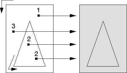
The following figure shows how the operating system determines the filled portion for the path shown in the figure before the previous one. Assume that both the rectangle and triangle were drawn in the same direction, whether clockwise or counterclockwise is immaterial. Both figures are filled, because the number of times the imaginary lines drawn from those points in the positive x-direction intersect the path boundaries is continuously summed. There is never a subtraction of a boundary tally to reduce the total to 0.
Parts of the path with nonzero tallies are filled; parts with zero tallies are not filled.
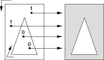
If two figures, for example in the following figure, are drawn in different directions, the tally for the inner triangle is 0 and the area looks exactly as it does in alternate mode.
Parts of the path with nonzero tallies are filled; parts with zero tallies are not filled.
Path Modification
To convert the current path to one that describes the envelope of a geometric wide line, use GpiModifyPath. The current geometric line attributes are then applied to the figures within the path. The line end, line join, and geometric line width attributes all must be set before modify-path or stroke-path operations begin, because it is during those times that the attributes are applied. Cosmetic line attributes of width and type have no effect on geometric lines.
GpiModifyPath accepts the path identifier (which must be 1) and the modification option MPATH_STROKE as input.
Subsequently, the modified path can be filled to display the geometric wide line, but only in winding mode. Alternatively, the modified path can be converted into a clip path, but again, only in winding mode.
Open figures within the path are not closed automatically. Figures not explicitly closed with GpiCloseFigure are drawn with line ends rather than line joins at their start and end points. If the figures within the path overlap, the geometric width envelope compensates so that the overlap portion is not drawn blank in XOR or exclusive-OR mode.
Now the geometric lines can be scaled.
Note: The current transforms are applied to the primitives inside a path bracket when the path is defined. This binds the path definition in device coordinates at that time. The path is unaffected by subsequent transformations, except for those (such as scaling) that affect the width of geometric (wide) lines. Since the geometric line width attribute is not applied until the path is converted into a wide line by GpiModifyPath or GpiStrokePath, the width of geometric lines is unaffected by earlier transformations directed at the path definition.
After creating a path bracket, geometric wide lines can be constructed by either:
- Stroking the path (GpiStrokePath),
- Modifying the path (GpiModifyPath), then filling the path (GpiFillPath).
GpiStrokePath is slightly more efficient, but GpiModifyPath and GpiFillPath offer more flexibility (by way of the fill options). After drawing the lines no alterations can be made.
Path-Stroking
To modify and fill the current path in a single operation, use GpiStrokePath. Then the path is drawn immediately to the output device, with the current geometric line attributes applied to the figures within the path. Certain device drivers can use this function to optimize storage.
GpiStrokePath automatically fills the path in winding mode with the current area pattern symbol. When GpiStrokePath is complete, the path definition is deleted from the device context.
GpiStrokePath is subject to the same constraints as functions that perform simple line modification:
- The line end, line join, and geometric line width attributes all must be set before stroke operations.
- Cosmetic line attributes of width and type have no effect.
- Any open figures within the path are not closed automatically.
- If figures are not explicitly closed with GpiCloseFigure, they are drawn with line ends rather than line joins at their start and end points.
- If the figures within the path overlap, the geometric width envelope compensates so that the overlap portion is not drawn blank when drawn in XOR (exclusive-OR) mode.
This function accepts as input both the path identifier (which must be 1) and the stroke option (which must be 0L).
When the operating system strokes a path, it draws a geometric line of specified width along the original figure that defined the path and then fills the wide line. If the original figure is not a closed shape, the operating system does not automatically close it before filling the path. The following figure shows the effects of GpiStrokePath on a box originally defined with normal (cosmetic) lines.
The broken line is the figure defined within the path. The solid lines show the path after it has been converted. Each line has a geometric width of n coordinate units, and the line joins have been defined as beveled.
After setting these attributes, the application can draw the line with GpiStrokePath. After the lines are drawn, an application can scale stroked paths with a scaling transformation.
As an alternative to the GpiStrokePath, you can convert the path using GpiModifyPath, which does not draw the path on the current output device. To draw a modified path, use GpiFillPath, which draws the path and fills it with the current area-fill pattern in winding mode. A modified path cannot be filled in alternate mode.
On some devices, it might be that the GpiStrokePath method works better than GpiModifyPath, followed by GpiFillPath.
Path Conversion to Clip Path
Clipping is the process an application uses to limit graphics output to a specific area (called the clipping area) of the display or page.
There are several clipping functions provided by the PM. However, if your application requires an irregular complex shape for a clipping area, it must define the shape with a path. To convert the path into a clipping boundary, use GpiSetClipPath. The clip path, as defined by this operation, becomes the current clip path for all subsequent drawing.
This function accepts a path identifier and one of two construction options as input:
- SCP_ALTERNATE (default)
- SCP_WINDING (must be selected if the path has been modified)
Unlike the path operations described previously, GpiSetClipPath accepts two different path identifiers:
- 1
- 0 (default).
The default path identifier of 0 (SCP_RESET) resets the clip path to infinity, which displays the picture without clipping. If this value is selected, the current clip path definition is discarded instead of stored.
For GpiSetClipPath, a path identifier of 1 (SCP_AND) causes the clip path to be redefined as the mathematical intersection of the stored clip path and the current path definition. For all other path operations, an identifier of 1 specifies the current path as the recipient of the operation. The only method of specifying the clip path as the current path, after GpiSetClipPath has been called, is to call GpiSetClipPath again: the first call with a path identifier of 0; the second, with a path identifier of 1. The path identifiers and the construction mode can be ORed together for certain effects.
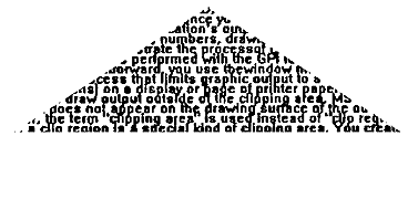
Any open figures within a path are closed automatically. The boundaries of the path are considered part of the interior, so any point on the boundary is not clipped. The following figure shows the result of clipping text with a triangular clip path.
Path Conversion to Region
To convert the current path to a region, use GpiPathToRegion. Then the new region can be modified using any of the region functions that allow the creation of irregular shaped regions.
Any open figures in the path definition are closed automatically by GpiPathToRegion. Upon conversion, the current path definition is discarded just like it is when being converted to a clip path. When GpiPathToRegion is complete, the path definition is deleted automatically.
This function accepts the path identifier (which must be 1) and one of two construction options as input:
- FPATH_ALTERNATE (default)
- FPATH_WINDING (must be selected if the path has been modified)
Using Paths
You can use path functions to:
- Draw geometric lines and filled polygons
- Draw outline text
- Create a triangular clip path
Drawing a Geometric (Wide) Line
The following figure is an example of how to draw a straight line, 10 units wide with rounded ends.
#define INCL_GPIPRIMITIVES
#include <os2.h>
void fncPATH01(void){
    POINTL ptl;
    HPS hps;

    GpiSetLineWidthGeom(hps, 10L);       /* Sets line width to ten              */
    GpiSetLineEnd(hps, LINEEND_ROUND);   /* Sets line end to round              */
    GpiBeginPath(hps, 1L);               /* Begins path                         */
    ptl.x = 7;
    ptl.y = 15;
    GpiMove(hps, &ptl);                  /* Sets current position               */
    ptl.x = 450;
    ptl.y = 15;
    GpiLine(hps, &ptl);                  /* Draws line                          */
    GpiEndPath(hps);                     /* Ends path                           */
    GpiStrokePath(hps, 1L, 0L);          /* Draws geometric line                */
} /* fncPATH01 */
Drawing Filled Polygons
The following figure is an example of how to draw an empty triangle within a solid rectangle.
#define INCL_GPIPATHS
#include <os2.h>
void fncPATH02(void){
    HPS hps;
    POINTL aptl1[4] = {       /*  Array of points for triangle   */
        50,  50,
        100, 100,
        150, 50,
        50,  50  };

    POINTL aptl2[5] = {       /* Array of points for rectangle   */
 25,  25,
 25, 200,
200, 200,
200,  25,
 25,  25 };

    GpiBeginPath(hps, 1L);                 /* Begins path                  */
    GpiMove(hps, aptl1);                   /* Sets current position        */
    GpiPolyLine(hps, 4L, aptl1);           /* Plots points for triangle    */
    GpiMove(hps, aptl2);                   /* Sets current position        */
    GpiPolyLine(hps, 5L, aptl2);           /* Plots points for rectangle   */
    GpiEndPath(hps);                       /* Ends path                    */
    GpiFillPath(hps, 1L, FPATH_ALTERNATE); /* Draws triangle and rectangle */
} /* fncPATH02 */
Drawing Outline Text
The following figure shows an example of how to draw text from an outline font with GpiOutlinePath.
#define INCL_GPIPRIMITIVES
#include <os2.h>
void fncPATH03(void){
    LONG lcid = 1;                            /* Identifier for font           */
    FATTRS fattrs;                            /* Structure for font attributes */
    SIZEF sizfx;                              /* Structure for character box   */
    POINTL ptl;                               /* Structure for starting point  */
    HPS hpsWin;

    fattrs.usRecordLength = sizeof(FATTRS);
    fattrs.fsSelection = FATTR_SEL_OUTLINE;   /* Specifies outline font        */
    fattrs.lMatch = 0;                        /* System determines font        */
    fattrs.szFacename[0] = 0;
    fattrs.idRegistry = 0;
    fattrs.usCodePage = 0;
    fattrs.lMaxBaselineExt = 0;
    fattrs.lAveCharWidth = 0;
    fattrs.fsType = 0;
    fattrs.fsFontUse = FATTR_FONTUSE_OUTLINE; /* Specifies outline font        */

    GpiCreateLogFont(hpsWin,(PSTR8) NULL, lcid, &fattrs);
    GpiSetCharSet(hpsWin, lcid);              /* Sets logical font             */

    sizfx.cx = MAKEFIXED(30, 0);              /* Width of character box        */
    sizfx.cy = MAKEFIXED(30, 0);              /* Height of character box       */
    GpiSetCharBox(hpsWin, &sizfx)             /* Sets size of character box    */

    GpiBeginPath(hpsWin, 1L);                 /* Begins path                   */
    ptl.x = 100;
    ptl.y = 200;
    GpiMove(hpsWin, &ptl);                    /* Sets current position         */
    GpiCharString(hpsWin, 7L, "Outline");     /* Establishes char. string      */
    GpiEndPath(hpsWin);                       /* Ends path                     */
    GpiOutlinePath(hpsWin, 1L, 0L);           /* Draws character string        */
} /* fncPATH03 */
Creating a Triangular Clip Path
The following figure shows an example of how to create a triangular clip path and then write text into it.
#define INCL_GPIPATHS
#include <os2.h>
void fncPATH04(void){
    POINTL ptlStart;
    HPS hps;
    LONG i;

    POINTL aptl[4] = {             /* Array of points for triangle     */
           35,  45,
          100, 100,
          200,  45,
           35,  45 };

    GpiBeginPath(hps, 1L);         /* Begins path bracket              */
    GpiMove(hps, aptl);            /* Sets current position            */
    GpiPolyLine(hps, 4L, Aptl);    /* Plots points for triangle        */
    GpiEndPath(hps)                /* Ends path bracket                */

    GpiSetClipPath(hps, 1L, SCP_ALTERNATE | SCP_AND);

    /* Write a block of text.                                          */

    ptlStart.x = 50;
    for (i = 50L; i < 110L; i += 10L) {
        ptlStart.y = i;
        GpiCharStringAt(hps, &ptlStart, 18L, "String of text!");
    } /* for */
} /* fncPATH04 */

